- Equipment required
- Installation
- Preliminaries
- Start of the program
- Create contours
- Zoom and displacing the graphic display
- Create texts
- Quick input of a simple Workpiece (F12)
- Manipulation of marked objects (enlarge, reduce, copy objects)
- Preparing the tool path computation, assignation of tools and layers to geometries / assigning of attributes
- Creating an operation list for the tool path computation; tool path computation
- Display of tool paths
- Output to the machine
- Import
- Surfaces
Download Demo-version of BESgrav
-
Equipment required - top
- Windows XP, Vista, 7, 8, 10 (x86 and x64)
- (some of the newest extensions needs at least Windows 7)
- Colour monitor and internet connection (only for installation), USB-Port or CD drive
- Mouse, track ball or something similar. The operation without a mouse is only efficient at the engraving machine if no geometry data is to be entered or edited.
- It is useful but not imperative that a mouse with three keys, is used, as the key in the middle may be used for many applications such as the abort function (like the ESC-key). When the middle key is pressed and the mouse is moved towards the boarder of the graphic display, the content of the graphic window is moved sideways.
- In case a mouse with a mouse wheel is used the display can be enlarged resp. reduced by turning the wheel. The wheel can be pressed. This has the same result as the pressing of the middle key of the mouse with three keys.
-
Starting the Installation - top
- By CD
- Insert the CD.
- Click onto "Start" and then onto "Execute".
- Select the name of the CD drive in the window "Execute" in the selection bar "Search in: ".
- In the window "Search" and there in the selection bar "Search in: " select the name of the CD drive.
- Now the data on the CD is displayed. The name of the DEMO version e.g. BESdemo.exe, the full version is named e.g. BESgrav*.exe.
- By a double click onto the name the file is selected. Now the window "Execute" is active again. Please click here onto "OK".
- The window "Initialization" appears briefly. Select the desired language in the following window "Select Language" and click "OK".
- Installation after downloading the Demo from the internet
- Load the Demo version of BESgrav from the internet. If the download is not yet carried out, please: Download Demo
- Execute the file you downloaded from the internet. For that you can for example search the file in the windows explorer and carry out a double click onto the name "BESdemo.exe".
- The installation on the computer starts.
- Continuation of the installation
- For the further procedure you will get information during the installation. If the installation is finished, please click once onto "Finish".
- A program group containing symbols for the program (little machine) appears as well as information files.
- For a quick program start you may copy the symbol of the little machine onto the desktop: Click onto the symbol with RIGHT mouse key and then select "Send to" and "Desktop".
- Or you may copy the symbol into the Task bar: Keep the CTRL key pressed and click the onto symbol with the LEFT mouse key.
Then, with the CTRL key still pressed, drag the symbol into the Task bar. - The Demo version is limited in its functions:
- The created workpiece can not be saved.
- Exportation is not possible.
- The menu items "Machine output" and "Manual control" may be called and the respective dialogs will appear, but it will not be possible to transmit the programs to the machine.
- No 3D-simulator is included
- No camera functions are included
- Notice for the installation of a Full version (not valid for the demo version):
- If a full version is installed for the first time, windows must be restarted afterwards to activate the installed drivers.
- A restart a necessary too, if a Demo version was installed previously.
- If you select a directory for the installation which contains already a version of BESgrav, no installation of a full version will be carried out but only an Update installation. The settings of the existing program will not be changed. Only the program is installed anew.
-
Preliminaries - top
- Notes for a peculiarity of the program when dragging a frame:
- With various Windows programs only a "long" mouse click is necessary: keep the mouse key pressed, drag the frame, release the mouse key.
This is not valid for the contour program! - Here the operation is as follows:
- With the first click the start point of the frame is determined. Now you can release the mouse key. The frame is attached to the mouse (rubber band mode).
- The size of the frame is fixed with the second mouse click (click and release).
- For the mouse key must not be pressed after the first click, the desired size of the frame can be entered via keyboard. This allows precise values. After the first mouse click (that is when the rubber band is attached to the mouse) the action can be cancelled by pressing the ESC key or the middle mouse key.
- Short explanation of the keys used in the short description:
- The CTRL key, will also be named as Strg key. In this manual it will be called Ctrl key.
The key is to be found in the lower left corner of the keyboard. If this key is pressed alone it has no function but only in connection with a tool or another key. If for example a mouse click is to be carried out together with the CTRL key, the CTRL key must be kept pressed while the mouse key is pressed. That is: - Press the CTRL key at first and keep it pressed,
- then carry out the mouse click and
- afterwards release the CTRL key.
- The SHIFT key is to be found in the lower left corner of the keyboard above the CTRL key. It has a double arrow Ý " on it. A second one is to be found below the ENTER key.
This key has, like the CTRL key, only a function in connection with a tool or another key and must be pressed before pressing the other key or clicking with the mouse. - The Enter key is also called Enter key. We will use Return. The key serves for confirming an entry.
- The DEL key is used to delete something.
-
Start of the program - top
- Start the program by clicking onto the program symbol
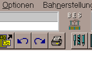
- Now you can see the working surface of the contour program. In the upper part of the working area the main toolbar is located:
The Main toolbar consists of 5 groups (from left to right): - Manual control
- Machine output
- File / New
- File / Open
- File / Save
- Import with last settings
- Export with last settings
- Undo
- Redo
- Print file
- Mark and manipulate
- Single lined text
- Multi lined text (Field layout)
- Diagnostics (information)
These five tools have three points at the bottom. The points indicate that by clicking onto such a tool a secondary tool bar is activated. If the corresponding secondary tool bar was activated, the button for the tool appears pushed in. The secondary tool bars are located to the left, to the right and at the bottom of the contour program.
They are:- Edit elements (at the left)
- Zoom display
- Create objects (at the bottom)
- Special tools (at the right)
- Font editor
- The positions at which the toolbars are located with the first program start are given in brackets
- Deletion of the marked objects.
- If you hover the mouse above a tool (button) a short information for the tool is given (tool tip / quick info).
In the above example the mouse cursor hovers above the tool "Create rectangle" at the left end of the toolbar "Create objects" at the bottom.
- If you need more help to a tool you must click onto the tool (it appears pushed in) and press the function key F1 (on the keyboard in the upper left corner). Afterwards a detailed description about the tool is displayed.
With the help for the tool "Create rectangle" you must select in the first help window whether you wish help for
the item - "Create rectangle with mouse and keyboard entry" or for
- Create rectangle via dialog".
- For this you click onto one of the green coloured texts. Equally you receive help for a menu item by pressing the function key F1. With the key combination Alt + D (keep the ALT key at the bottom of the keyboard pressed and type D) for example you activate the pull down menu "File". (For opening a different menu you must type the character in the menu bar that is underlined). You can select a menu item or another column of the menu bar by using the cursor keys. By pressing the F1 key you receive help for the menu item that is marked by a coloured bar.
- Start the program by clicking onto the program symbol
-
Create contours - top
- Example "Create rectangle":
- In the lower toolbar "Create objects" activate the tool "Create rectangle" at the left side by clicking onto it.
- Input by mouse
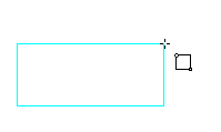
- Click within the drawing area at the position where the first corner of the rectangle shall be placed. Release the mouse key afterwards.
- When dragging the mouse a rubber band-rectangle is displayed in light blue colour. One corner of the rectangle corresponds to the first mouse click, the opposite one to the position of the mouse cursor.
- If the SHIFT key is pressed additionally the first clicked point becomes the centre of the rectangle.
If the CTRL key is kept pressed a square is displayed.
In case the SHIFT key and the CTRL key are kept pressed together a square with the centre point on the first clicked point is displayed.
If the entry shall be cancelled while the rubber band is attached to the mouse the ESC key must be pressed (the key in the upper left corner of the keyboard).
If you use a mouse with three keys that is installed according this function, the action can be cancelled by pressing the middle mouse key.
Using a mouse with a mouse wheel the wheel must be pressed briefly. - The second click with the LEFT mouse key determines the final size of the rectangle. The rectangle is finished and displayed in black.
- Entry via dialog
- The dialog of the rectangle tool is opened by pressing the RIGHT mouse key. The first click with the mouse is taken over as X- and Y-value in the dialog but can be edited here afterwards. In the dialog various possibilities for an entry can be found. For example you can determine the rectangle by entering its height and width. You can also determine where the rectangle shall be placed in relation to the position of the mouse click: around the centre, at one of the corners or at the centre of one of the sides.
You receive detailed information when clicking onto "Help button" in the dialog. - Example "Create Polyline":
- The Polyline tool is the third from the left side in the lower tool bar. The tool must be clicked upon to activate it.
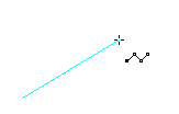
- Click within the drawing area with the LEFT mouse key. Thus the start point of the polyline is determined. Release the mouse key.
- By moving the mouse a rubber band line is generated the start point of which is attached to the first mouse click. The end point moves with the mouse.
- By pressing the SHIFT key a horizontal or vertical line can be generated as well as a line of 45 degrees. When the line for example is nearly horizontal and you press the SHIFT key then, the rubber band changes its position and an exactly horizontal line is created.
- With the next mouse click the line is finished and displayed in black. The rubber band is now attached with its beginning at the end of the first line and with its end at the mouse cursor.
- With the next mouse click another line is created etc.
- If no more lines shall be drawn the rubber band mode is cancelled by:
- Pressing the ESC key (at the upper left corner of the keyboard)
- Pressing the middle mouse key (resp. the mouse wheel) or
- A new click exactly onto the last entered point of the polyline.
- Continue an existing contour or connecting to it.
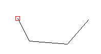
- In the example to the right a polyline was drawn which consists of three straight lines.
If you move the mouse above the left end a red square appears.
Such a square appears always in case the mouse hovers above the node point of a contour and if the node point is identified. Here the square is red because it is a start point.
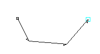
If an intermediate point or an end point is hovered above a light blue square is displayed.
In the example to the right the mouse was moved above the right end of the contour:
In this picture the display of the contour direction was activated additionally. You can do this by means of the button at the lower right corner in the graphic display. The picture shows this button pushed in (active):
The start point of the contour is marked with a black square. At each node a little arrow is to be seen which indicates the direction of the contour.
If the polyline shall be closed by a further line, it is useful to close the contour in the right direction. If you place the mouse cursor onto the start point of the contour at which a red square appears, a straight line in the opposite direction of the contour would be created when drawing the connecting line.
In case no Path generation is carried out (Sunk engraving) the machine would process the contour just as it is that means the contour will not be processed in one operation but the machine will raise in between and begin the contour anew. With the Path generation changes of the contour direction are corrected but it is more efficient to resign from changes in the direction to achieve a better overview. - Working with the grid
- When entering coordinates via mouse "odd" values are produced. If you wish for example to use only coordinates with even mm-values you should use the grid. In the lower right corner of the graphic display the field of switches for several functions is to be found. The switch for the grid is the left on.
With the LEFT mouse key the switch can be clicked on or. off. Clicking with the RIGHT mouse key onto the switch opens the dialog for the grid. Here four different grids can be adjusted and one can be activated.
If for example a grid with a distance of 1mm in X and in Y is adjusted and activated, only coordinates rounded to 1mm are displayed.
Pressing the function key F2 switches the grid on or off very fast, even in case a rubber band is attached to the mouse.
You get further information about the grid when you open the grid dialog and then click upon the button "Help". - A grid can be projected onto an existing geometry and this way, for example, divide a rectangle into fields of the same size to position texts with the same distance. For this you activate the tool bar "Zoom display"
by clicking onto the button in the main tool bar.
The Zoom tool bar is displayed at the right side (as long as the position of the tool bar is not changed in the menu "View").
The tool for orientating a grid towards a geometry is the last tool in the tool bar.
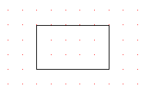
f you draw a rectangle and select this tool afterwards, two opposite corners of the rectangle must be clicked at one after the other. After that the dialog opens automatically.
The coordinates of the corners which are clicked by the mouse are filled in the entry fields at the lower part of the dialog. The values are to be taken over into one of the grids by clicking onto one of the buttons 1 to 4.
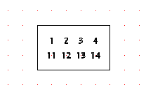
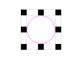
In the corresponding grid the values for the divider must be still adjusted. If you wish to install 2 rows of drillings or texts in the rectangle and four of which in one row at a time, then for the divider in X' '5 must be entered and for the divider in Y '3'. After clicking onto OK in the dialog the grid is displayed (see picture):
Within the rectangle 4 grid points are visible in X and in Y there are two rows of grid points.
If you now draw something and place the mouse cursor next to a grid point, the mouse pointer will snap exactly to that grid point.
Thus, for example, simple texts can be positioned to the grid points: - Entry of precise coordinate values via keyboard. Input box for absolute and relative coordinates.
- Input box for absolute and relative coordinates:

In the upper right area of the graphic display values are represented. The upper row displays absolute values referred to the zero point at the bottom left of the workpiece (dashed lined frame). These are the X- and Y-values in mm (as far as no switching to Inch was carried out). The polar coordinates with angle and distance between two points follow. Angles are mathematically defined: 0° corresponds to horizontal from left to right; +90° corresponds to vertical from bottom to top.
In the lower row the values are entered relatively to the last input. If the input is carried out by Enter key or mouse click, the relative display is set to zero.
Now you can read off the distance of the mouse relative to the last input.
This display can also be used to measure something. If you click with a tool, for example with the Diagnostics tool, onto a corner point , the relative display is set to zero. If you move the mouse to another point the distance of the mouse position to the clicked corner point can be read off. - Keyboard entry in the input box for value entry:
With the entry of coordinates using the mouse it is difficult to enter precise coordinate values.
If the coordinates are submitted for example from a drawing you can enter the values instead of using the mouse use the keyboard to enter the values in the value entry box.
- Absolute entry
Example: If you activate the tool Polyline in the value entry box in the upper left the text "Polyline 1. point" appears. If you now enter the value for example "10" it is shown in the value entry box.
This is the value for the X-axis. By pressing the Space key or the Tabulator key the red cursor jumps into the right entry field. Here you enter the value for the Y-axis, for example "20".
The entry must be confirmed by pressing the ENTER key.
The mouse cursor jumps to the entered position. If you move the mouse a light blue rubber band appears (it is not necessary to move if only keyboard input was made).
Now the coordinates for the next point of the polyline can be entered. - Relative entry
At least one point of the polyline is entered and the rubber band is attached to the mouse. Now a line shall be drawn horizontally with a length of 30 mm. At first you enter an "R" must be entered as capital letter.
In box entry fields of the value entry box the letter "R" is displayed that means that both entry fields are switched to relative entry.
Pressing the key "R" anew switches back to absolute entry.
If you press the key "R" together with the SHIFT key the switching is only valid for the entry field in which the cursor stands.
Now enter the value "30", for the line shall have a length of 30 mm. Pressing the Space key or the Tabulator key the cursor jumps into the Y-axis field. Here you enter "0" for the line shall run only horizontally that is it has no extension in the Y-direction.
After pressing the Enter key the horizontal line is shown. - Polar entry
Pressing the key "P" the program switches to polar entry. Instead of the X- and Y-values the angle and the length (amount) are entered. The polar input can be combined with the relative input. With this the angle and the length of the desired distance can be entered. - You may continue the polyline as long as you wish or you cancel the drawing by pressing the ESC key or the middle mouse key.
- Pressing the key "L" you fetch back the last entry into the entry field to edit it.
- It is possible to transfer one value each via the clipboard into the entry field.
- Computation within an entry field is possible. The characters " + - * / " can be used for this, for example: "37,5/2".
- The character "%" relates an entry to the workpiece dimensions. If you enter for example "%50" for X and for Y a point exactly in the middle of the workpiece is achieved.
-
Zoom and displacing the graphic display - top
- To get a closer view at certain spots you may enlarge (zoom) them. For this you place the mouse at the spot that shall be viewed more close.
Pressing the key F5 enlarges the spot, pressing F6 reduces
If you possess a correctly installed mouse with a mouse wheel, you can enlarge and reduce the spot by turning the wheel.
If you keep the SHIFT key pressed while turning the mouse wheel the degree of zooming is reduced.
If you move the mouse towards the border of the graphic screen while the middle mouse key resp. the mouse wheel is pressed, the image section is moved sideways.
You can also move the view by pressing the F7 key. Doing this the position of the mouse is placed to the middle of the screen.
Additionally a dislocation of the view is possible by the 4 cursor keys. Keeping the CTRL key pressed while pressing one of the cursor keys moves the view in the corresponding direction.
If you keep the SHIFT key pressed additionally to the CTRL key the degree of the displacement is reduced.
(If the a cursor key is pressed without an additional key the cursor in the value entry box is moved) - There are two possibilities to renew the graphical display:
A mouse click onto the lettering above the little symbol of the machine caries out a total view on the adjusted workpiece dimension.
A mouse click onto the little machine symbol does not change the current view (e.g. after zooming in), but only a refreshing of the view is carried out
- To get a closer view at certain spots you may enlarge (zoom) them. For this you place the mouse at the spot that shall be viewed more close.
-
Create texts - top
- At the top of the main tool bar there are two tools for creating texts. For single line texts the text tool is used:
Activate the tool and click onto the position at which the text shall appear. A dialog is opened in which you enter the text. Select a font in the selection window.
- (TT) marks TrueType fonts of Windows.
- (ZF) marks the font format of BESgrav.
- (PG) marks ProGrav fonts of Kuhlmann.
Clicking the OK button the dialog is closed and the text is displayed in the graphic window.
Using the mouse wheel or the function key F5 the view can be enlarged to take a closer view on the text.
Spacing:
From a certain degree of enlargement on in front of every character a little square appears. These square are used for the spacing, that is the insertion of additional space between the characters.
- If you click into a square a light blue square is attached to the mouse. This square can be moved (if necessary the grid must be switched off with F2). If you click again the square is fixed at the desired position for the new space between the characters.
- If you wish to call the dialog again for example to carry out changes in the text, you must click again into the text.. Keep in mind not to click into one of the squares! Using the RIGHT mouse key to click the squares will be ignored.
- Multi line texts are entered using the Field layout tool:
After you have selected the tool you determine by two mouse clicks a frame in which the text shall be placed.
After the second mouse click a marking frame appears containing 8 round markers, which can be gripped with the mouse e.g. for changing the size (1st mouse click for the grip, second click to fix the position).
If you click into the frame with the Left mouse key, a single text line can be inserted.
If you click between two existing text lines the new text will be inserted at this place.
Clicking with the RIGHT mouse key opens the dialog where you can enter all text lines at the same time.
Clicking onto "OK" closes the dialog and the text is displayed. At first all text lines are formatted with the same font, the same character height etc.
To carry out changes for all text lines you open the dialog again by clicking with the RIGHT mouse key in to the frame.
To carry out changes (e.g. the changing the character height) only to the first line, you mark this line by clicking onto it with the LEFT mouse key. The line is now highlighted. Another click opens the dialog for this single line is opened and you can carry out the desired changes. - Taking over texts from the clipboard.
Text can be taken over quickly from other software programs using the clipboard.
For this the text in the other software must be marked and copied into the clipboard (for example with the key combination CTRL + C).
Now activate the Text tool in BESgrav. Keep the SHIFT key pressed and click with the RIGHT mouse key at the position at which the text shall be inserted.
If, for example, the font shall be changed you must click with the RIGHT mouse key (without SHIFT key) within the text to open the dialog. The changes you carry out here are valid for all text lines to be inserted from now on.
If there are several text lines in the clipboard, with every click of the RIGHT mouse key while the SHIFT key is kept pressed a new text line is inserted. The subsequent text line is displayed in the status line.
An acoustic signal is to be heard when all text lines are inserted from the clipboard. With the next mouse click the first line of text would be inserted again. The texts in the clipboard may contain Unicode fonts. For this in the dialog a corresponding Unicode font must be selected.
See also: Notes about Unicode fonts in one of the following items.
In case the tool Field layout for several text lines is activated, a frame must be clicked at first.
If the RIGHT mouse key is clicked together with the SHIFT key, all text lines from the clipboard are inserted in one step. - If only a part of a text line shall be edited (e.g. assign a different font) the tool "Local text editing" from the "Special tools" bar must be selected.
Example. - If for several lines of text the same changes shall be carried out (e.g. assign a different font), this can be done for all text lines at once. You select the tool "Global text editing" for this (in the tool bar "Edit elements").
- Notes about Unicode fonts:
It is possible to use Unicode characters.
The taking over takes place via the clipboard, for example from the program 'Character table' or as numeric input.
It is for example possible to insert Chinese characters with this.
At the moment texts containing Unicode codes can be taken over using the key combination SHIFT + RIGHT mouse key like described above under 'Taking over texts from the clipboard'.
Although it is possible to insert the text into the dialog via clipboard, but if the text contains Unicode the characters can not be represented correctly (this shall be corrected in a later version of BESgrav)
Further information about Unicode are available in the Manual of BESgrav.
Further general information about Unicode are available under http://www.unicode.org.
- At the top of the main tool bar there are two tools for creating texts. For single line texts the text tool is used:
-
Quick input of a simple Workpiece (F12) - top
- To create a simple plate with several lines f text you use the function key F12.
After pressing the F12 key you are lead stepwise to the finished plate. - At first a dialog appears in which you enter the workpiece dimension and a border.
- Subsequently the dialog for the Field layout is opened. Here the data of the desired text and the text itself must be entered.
- The peculiarity here is that the dialog must not be opened always anew. By pressing the button 'M-Output' a graphic display is carried out in which you can control the result. The machine output is started immediately after pressing the Enter key. Afterwards the dialog is opened again automatically. Plates can be created one by one quickly without leaving the dialog.

After each entry of a new text the button must be pressed again.
This rapid output is however only suitable for hollow fonts (Demo V). In case a tool path computation must be carried out, the dialog must be left at first by clicking onto "OK", then the path computation must be carried out and afterwards the machine output must be called.
- To create a simple plate with several lines f text you use the function key F12.
-
Manipulation of marked objects (enlarge, reduce, copy objects) - top
- Draw for example a circle with the tool from the tool bar "Create objects". Eventually you must clean the graphic window before by clicking the menu item "File" and the sub-item "New".
The first click with the active tool determines the position of the centre point.
Now drag the mouse to make a circle. The second click fixes the size of the circle. - Activate the Mark tool from the main tool bar.
- There are two possibilities to mark something:
- Directly clicking:
This method is appropriate if only one object shall be marked.
Click with the tip of the mouse cursor directly onto the contour to mark the object.
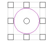
A marking frame with 8 black squares appears.
If you click an object which is not marked yet while the SHIFT key is pressed, it is added to the marking. - Dragging a frame:
This method is suitable in case several objects shall be marked.
Clicking besides a contour attaches the rubber band at the mouse which can be stretched over one or more objects.
A second click marks everything that is inside the rectangle of the rubber band frame.
- Both methods can be mixed: Further objects can be marked by clicking onto them while the SHIFT key is pressed. It is also possible to draw up another marking frame while the SHIFT key is pressed.
- You can carry out manipulations with the Marking frame.
If you click onto one of the black squares the size of the object can be changed.
If you keep the SHIFT key pressed while the rubber band is attached to the mouse, the object is distorted around its centre.
If you click onto one of the corners the distortion is carried out in X and Y at the same time. Keeping the CTRL key pressed while doing this X and Y can be distorted differently.
A second click displays the object with its new size. - If you click with the RIGHT mouse key a dialog is opened in which the manipulations are to be made.
If you click in the dialog onto the buttons at the top, the corresponding pages of the dialog are opened. - When the object is marked with the marking frame, by clicking into the frame with the RIGHT mouse key the object can be gripped and displaced (do not click onto the black squares).
Depending on what spot in the frame you clicked the object is attached differently at the mouse.
When it is attached to the mouse the position can be changed by using the cursor keys.
Pressing the ESC key or the middle mouse key cancels the action.
A second mouse click fixes the position of the object. - If you keep the CTRL key pressed while clicking into the frame a copy of the object is made.
In this case the original circle is preserved. A second one is created at the position you click the second time with the mouse.
You can repeat this until the necessary number of copies is reached. But in case many copies are recommended it is more efficient to work with the cloning function (To be found in the manipulation dialog which is to be opened with a click of the RIGHT mouse key when an object is marked. The buttons in the middle of the top of the dialog belong to the clone function. If you activate one and click onto "Help" you get adequate hints). - It is also possible to carry out manipulations using the keyboard. Take a look at the value entry window in the top left of the graphic window: Above the entry fields it is indicated what kind of entry is possible. You can, for example, enter the factor for distortion by means of the keyboard after clicking onto one of the black marking squares. If for example a precise reduplication with factor 2 shall be achieved, you can do this more exactly and simply by entering values via keyboard.
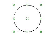
The entry of "-1" mirrors the object without changing the dimensions (in the dialog with "Rotation" you can de-activate the Mirroring). - If an object was marked and the marking is removed by pressing the ESC key, 9 little crosses appear instead of the marking. These are the auxiliary points, which can be used to adjust other objects.
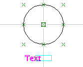
The auxiliary points only are visible in case the corresponding button in the lower right part of the graphic display is clicked active: - If another object (e.g. a text below the circle) is marked afterwards, the object can be adjusted to the circle:
Mark the text below the circle. Click into the frame close to one of the black squares in the middle of the top or bottom. Move the frame a little bit sideways. If you now keep the SHIFT key pressed, the text can only be moved sideways.
If you move the mouse to the centre of the circle the text snaps to it sideways. - Is an object marked with the frame and the 8 black squares the manipulation mode can be switched by a double click onto one of the black squares. The squares are no longer filled.
If you grip a square in the middle of one side the object can be inclined.
Gripping a corner the object can be rotated. The rotation angle can be entered in degrees via keyboard.
The rotation centre point can be moved to a new position for the rotation. - In case an object is marked either with the Mark tool or with the Attribute tool while you click onto the tool "Delete marked objects" or press the Del key the object is deleted.
The deletion and other actions can be made undone. An undone (Undo) action can
as well be redone (Redo).
You do this with one of the two buttons in the main tool bar containing a curved arrow each.
- Draw for example a circle with the tool from the tool bar "Create objects". Eventually you must clean the graphic window before by clicking the menu item "File" and the sub-item "New".
-
Preparing the tool path computation, assignation of tools and layers to geometries / assigning of attributes - top
- There are different fundamental ways to put out tool paths to the machine.
In the most simple case the tool paths are put out to the machine unchanged, only the engraving depth is adjusted.
The delivered engraving font DEMOV is suitable for the Sunk engraving.
Here, the contour consists only of a single line (in the blow picture the left font).
The TrueType fonts are outline fonts. the letter is represented by an area which is surrounded by a contour (the right font in the upper picture, here font Arial).
The sunk engraving of the font is carried out with a tapered cutter. In doing so the contour is widened to the left and right of the contour and results in a certain width depending on the shape of the cutter and the engraving depth:
If for example the cutting depth is increased the width of the contour increases too.
With the outline font the cutter does not travel onto the contour, because only within the contour the material shall be removed. For this the tool paths must be computed. The width of the contour that constitutes the font results from the font itself.The tool path computation is an enlargement of the basic module. This function must be purchased separately.
Modules like for example GK2D contain the tool path computation, at least in a simple style.
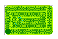
In the picture a rectangle is cut clear by several transposed tool paths:
Here the outer milling path travels to the inside of the contour, transposed by the half diameter.
Even if you increase the engraving depth a little and you work with an engraving cutter the rectangle will have the same dimensions. The tool path computation will correct the distance of the tool to the contour accordingly. - The program must be made known how the contours shall be processed, that is whether they shall be put out as sunk engraving directly to the machine or whether tool paths shall be computed.
If you intend to only process simple sunk engravings with one engraving depth and one tool in principal, you can switch to "Direct output" in the menu "Path generation" in the dialog "Settings" at the item "Geometry without attribute for".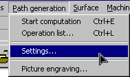
Next you draw geometries and click the button "Machine output:":
By the machine output the geometry data is send directly to the machine without computation of tool paths, that is without cutter radius compensation.
For the engraving depth the presetting is taken that is to be adjusted in the menu "Options", dialog "Presettings".
With Direct output no attribute must be assigned.
The further explanations in this item '10' will not required in that case. - If however different engraving depths and tools shall be used, attributes must be assigned to the geometries. Parts of the geometry is assigned a tool and an engraving depth. The assignment of attributes is explained from the item after next.
- If different kinds of tool paths shall be computed, e.g. the clear cut of different geometries with different tools (pocket milling), you must set up an operation list. Here the different steps of processing are listed together with the tools and engraving depths.
For enabling the list to access the geometries aimed different attributes must be assigned to them. - Attributes are assigned using the Attribute tool
With this tool geometries can be clicked at directly and thus be marked or you drag a marking frame around all geometries to be marked. The marked geometries are coloured in magenta (pink). Different from the Mark tool no marking frame appears but the Attribute dialog opens instead.
In case only a single geometry was clicked the dialog must be opened by clicking with the RIGHT mouse key.
If you marked the geometries with a frame the dialog opens immediately.
In the dialog you basically determine at first whether the Direct output or whether a tool path computation via operation list shall be carried out.
For the Direct output you can already determine here: the tool, the engraving depth and the technology (infeed, spindle RPM etc.).
If a tool path computation shall be carried out (cutter radius compensation, pocket milling, cut out etc.) the geometry must be set to an Operation list.
Note: If areas shall be clear cut (pocket milling) the area to be clear cut must be surrounded by a closed contour. No gaps are allowed.
It is also possible to assign layers. For better overview colours can be assigned to the layers. This serves also for certain computations for specified contours (layers).
If for example one rectangle shall be clear cut wit a different tool than another one , the first rectangle can be set to layer 1 and the second rectangle to layer 2.
By the Operation list layer 1 with a specific tool is processed at first and afterwards layer 2 with another tool.
Notes:
The Path generation is an additional tool, which is not included in the Basic module or the Beginner module.
Layers can not be assigned with the Beginner module, thus the coloured representation is not possible there.
- There are different fundamental ways to put out tool paths to the machine.
-
Creating an operation list for the tool path computation; tool path computation - top
- For very simple workpieces an operation list is not necessary, see Preparing the tool path generation.
The moment tool paths shall be computed (cutter radius compensation), an operation list is required.
With a pour sunk engraving where different engraving depths are required, an operation list is also not necessary.
All contour which shall have the same engraving depth, must be assigned an attribute. If the attribute is adjusted to 'sunk', the tool and the engraving depth can be assigned directly.
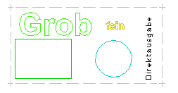
For every single special engraving depth an attribute is necessary. - Load example: Please load the workpiece file "_4ebenen.wst" by clicking onto the button "Open file" in the main tool bar.

In the dialog the file is loaded by a double click onto the name.
The workpiece is displayed afterwards:
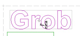
If you move the mouse with the Attribute tool
active over the text "Grob" a rectangle appears around this text.
It indicates that here is a text that is not resolved into contours, that is it is treated as an object.
If you click inside the rectangle with the LEFT mouse key, all parts belonging to this attribute is marked in magenta:
In the status line a message appears indicating how the attribute is adjusted. In this case it is: "geometry for operation list, layer: 1".
If you click onto the contour of the green rectangle the message is: "Geometry for operation list, layer: 3".
a corresponding message is displayed for the other contours. Please notice that with texts you must only click within the area of the rectangle. With contours you must click exactly onto the contours. How exact it must be you can identify when moving the mouse over one corner of the contour. If the little square appears it is exactly enough.
If you click with the RIGHT mouse key onto the calculator,
in the midst of the upper part of the program, a dialog containing the operation list appears: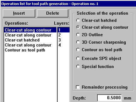
Here the single operating steps are listed. At first the layer 1 will be clear cut along the contour, afterwards layer 2 is processed etc.
Clicking with the mouse onto a processing step so it is highlighted (in the upper example the first step) the dialog shows the data for this processing step, that is the kind of operation, the tool, the engraving depth etc. - Clicking with the LEFT mouse key onto the calculator starts the computation of the tool path.
During the tool path computation test outputs are carried out at those steps the calculation is working with.
- For very simple workpieces an operation list is not necessary, see Preparing the tool path generation.
-
Display of tool paths - top
- If for a workpiece the tool paths are computed, they can be displayed by clicking onto the little green button at the right of the lower part of the graphic window.
2D paths are displayed in green colour, 3D paths like dip-in moves are coloured blue. With every redraw, therefore with zooming too, the tool paths are displayed anew until this function is switched off by clicking onto the button again.
Adjustments for the display can be made in the menu "View" under "Tool path settings".
- If for a workpiece the tool paths are computed, they can be displayed by clicking onto the little green button at the right of the lower part of the graphic window.
-
Output to the machine - top
- With the Demo version no output to the machine is possible!
(An export is also not possible!) - Previous to an output to the machine, the machine must be prepared, as far as this is not be done by the deliverer.
In the menu "Machine" and the dialog of "Controller settings" the "Controller type" must be selected at first.
If the type is changed you are requested whether to use the standard setting for the new controller.
If the presettings must be changed a click onto the button "Help" offers detailed information for this.
If you work with a Gravograph machine and a vice you carry out the settings in the dialog of the button "Divers". - After the installation there are eventually further settings to be made for peculiarities like for mirroring or rotating of the workpiece.
This is to be done in the menu "Machine" in the dialog of the "Machine preparation".
Here, for example, the Rapid traverse speed of the machine can be entered too. - In case a machine is controlled directly (no output to file) the "Manual control" must be called before the output of the tool paths to the machine.
The corresponding dialog appears.
The main task of this dialog is to adjust the workpiece zero point. That is the position the lower left corner of the machine is located. The adjustment can be carried out in this dialog or, like with some other machines as there are Cx268, BES/T and BES/P, at the machine. The values adjusted here are transferred back to the PC.
In the Help you learn perhaps peculiarities about your machine. Especially in case your machine is equipped with a tool length sensor, a tool changer or something similar an introduction and installation should be carried out by the manufacturer. - The output of the file is started by clicking onto the button "Machine output"
If your machine is connected directly, the data is send directly to the machine. Here the Start button must be pressed eventually to start the processing.
In case "Output to file" is adjusted, a file will be created. The file must be transmitted to the machine together with the program belonging to the machine.
With bigger workpieces a window appears during the output in which the outputs are counted.
- With the Demo version no output to the machine is possible!
-
Import - top
- By clicking onto the button "Import" with the RIGHT mouse key a dialog opens. Here you can select the desired format for the import.
For some formats special settings are possible.
The "Joining tolerance" is used to close little gaps. With the data of some CAD-system very small gaps within the contours may occur for example because it was drawn on the screen and certain existing contours were not met precisely again. If this tolerance is adjusted a little bigger than the existing gaps, the gaps will be automatically closed. If the tolerance is adjusted too big unusable falsifications of the contour are produced! - After clicking onto "OK and import" the file selection is displayed.
When the file is selected the import is carried out.
Before the import of image files a dialog is opened containing the data of the file and special setting possibilities. - After certain imports every part of the import is marked. Thus the imported geometry can quickly be positioned.
- Later too, all geometries imported together can still be marked together:
For this you activate the Mark tool and click onto the desired contour. Subsequently you must keep the CTRL key pressed and click repeatedly onto the same spot.
Doing this the marking raises within the structure. At first only one object is marked, afterwards perhaps everything that was imported together. At least the whole workpiece is marked.
- By clicking onto the button "Import" with the RIGHT mouse key a dialog opens. Here you can select the desired format for the import.
-
Surfaces - top
- This module serves for the processing of 3D curved surfaces and for the engraving onto those surfaces.
Processing and engraving can be carried out separately or combined in one production process.
The software module "Surfaces" must be purchased separately, however it is included in the software module GKO. - The input of a workpiece containing a surface can look like this:
- At first a normal plane workpiece with all contours is programmed.
If the surface itself must be processed, an additional contour for the area for the milling process must be entered. In the most simple case you specify a rectangle in the dimensions of the workpiece.
With a surface containing a sphere for example, it may be effective to specify a circle in the midst of the sphere as a limitation for the processing of the sphere.
This is the case in the following example. You achieve that the sphere is travelled around with a constant distance by the cutter. This serves for a good surface quality. In the example "bsp-kugel.wst" only a part of the sphere is processed. You do not see the total visible part of the sphere to be milled. - Assign a layer number to the limiting contour that is different from all other layer numbers of the workpiece (however, you should not use layer number 0 here!)
The shape of the surface is determined in the menu "Surface" under "Select & define".
A surface is build up of one or more partial surfaces.
A partial surface may determined mathematically , for example as sphere or it may exist as file in different formats (STL, SGR, VRML, image file). Such a file can descent from the scanning of a existing surface (see menu "Scanning") or from a foreign program.
Mathematically defined surfaces and surfaces from a file can be combined among themselves or mixed.
They can be combined positively like for example as if a sausage is laid upon a curved dish. The sausage lies upon the dish. Or the surfaces can penetrate each other, like a skewer is pushed through a sausage.
The final 3D shape is determined by the order of the overlays and the way of overlays referring to the previous surfaces.
As an example a sphere shall be programmed:
At first you specify a workpiece dimension of 100 mm x 100 mm (menu "File", "Workpiece dimensions").
In the menu item "Surface" you select "Select & Define".
A dialog is opened containing a list up to 14 partial surfaces. At the partial surface no. 1 you click onto "Edit".
Now you select the type of the partial surface. The sphere is preset.
Leave it at that and click onto "Definition".
The centre point is preselected to the centre of the workpiece. The radius of 50 mm is adjusted appropriate to this.
For the arc height is at 25 mm, the sphere will rise a quarter above the surface.
Leave dialogs "Definition" and "Partial surface" by clicking "OK".
The dialog "Surface definition" is displayed again.
If you click at the first partial surface onto "View" the sphere will be displayed. With a combination of several surfaces the button "View" displays a single surface of the combination.
Quit the representation by clicking "OK".
Quit the dialog "Surface - definition" with "OK" too.
Save the workpiece for example under the name "Sphere".
Subsequently you are asked whether to re-calculate the surface grid. Please answer with "Yes".
After the computation that section of the sphere is represented, that rises above the plane workpiece.
The representation can be rotated and inclined using the cursor keys.
Keeping the CTRL key pressed the representation can be moved sideways.
Together with the SHIFT key the degree of rotation and inclination is reduced.
Clicking the button 2D/3D in the lower right part of the graphic window you return to the 2D representation.
Switching to 3D is only possible with workpieces that contain a defined surface.
The function "Background picture" can be activated under the menu "Surface", "Select & Define", "Options". During the 2D display a representation of the surface as bitmap is shown.
In the example "bsp-kugel.wst" a circle is defined to generate concentric clear cut paths in the area of the sphere. Finally a text is created onto the sphere. Explanations for this are to be found in the following items. - Via the menu "Transfer tool paths" the hitherto plane tool paths will be transferred onto the curved surface.
In the dialog two operation lists of the path generation are to be found.
The first operation list assumes a solid piece of material and processes the surface out of it..
This can be done for example using the function "Clear cut, hatched". The material is removed in several roughing steps down to the surface.
if for example with every clear cut step 1 mm of material is removed, this 1 mm will be removed over the total defined clear cur area until the surface is reached.
In case the surface is a sphere, the highest point would be reached at first in the centre. The clear cut paths are reduced in the cutting depth that way, the highest point of the sphere will always be overrun
For a good surface quality it is necessary to specify the cutting paths very narrow.. However, this increases the processing time. With the first processing step it is therefore useful to adjust a high percentage for the cutter usage and for the Z-offset a value of same tenth millimetres. The high cutter usage serves for a quick processing. The Z-offset leaves a rest of material above the defined surface.
In a second processing step the cutter usage is set to a far smaller value, e.g. 5%. Thus many narrow cutter paths are processed that serve for a good surface quality. The Z-offset must be set to 0, for the exact surface shall be processed now. The first processing step operates in steps towards the surface like specified in the technology object.
Refers the second processing step to the same layers, the program recognizes automatically that only the last step is to be processed for the material is already removed.
It is possible to use different tools for roughing and finishing.
In the dialog no cutting depth can be entered, because it is not intended to engrave with a certain depth into the surface but the surface itself shall be processed. How much of the material is to be removed with each processing step (roughing depth) is to be defined in the technology object.
It is very difficult for example to position cutter paths in that area in which the sphere meets the surface. Because for the processing of a surface the sphere cutter is usually used, it is not possible to process a precise corner. On the other hand the preciseness of the surface in this area bears a problem.
Because the cutter does not touch the surface always with the same spot, a compensation is necessary. The compensation is calculated by means of a grid. To achieve a good quality at those critical spots the grid must be adjusted as fine as possible. A too fine grid, however, increases the computation time and the time for the graphical display intensely. Eventually it is possible that you work with a rough grid during the creation of a workpiece. Only just before the milling you adjust the grid more fine and let it calculate anew. The grid is to be adjusted in the menu "Surface / Select & Define / Options". The grid influences the preciseness of the 3D compensation during the processing of the surface. The cutter paths. The cutter paths on this surface (according the subsequent 2nd operation list) are transferred correctly according the mathematical definition of the surface.
The second operation list starts from the finished surface. Like in the 2D level tool paths are computed, which are transferred to the surface.
It is the same operation list like in the menu "Path generation / Operation list" that was used hitherto for 2D engravings. By means of this list the paths are calculated at first in 2D. Here again an engraving depth can be given that defines the depth from the surface.
If for example a line is engraved with a constant engraving depth of 0,5 mm, it has a depth of 0,5 mm at each spot. With the transferring onto a surface , for example in the shape of a sphere, the line follows the curved surface of the sphere that way, the line keeps the depth of 0,5 mm at every spot.
In the example the text "Sphere" is transferred to the finished surface.
If you start the transfer of the tool paths the activated operation lists are computed at first. Afterwards the generated plane paths are computed onto the curving of the surface.
Now the output to the machine can be carried out as usual for a plane workpiece. - Please keep in mind when working with 3D surfaces:
- Changing the display of the 3D surface and of the tool paths:
Menu "Surface", submenu "View" - In the 3D display you can only use:
The zoom tools And the function keys F5, F6 and F7. - Switching between 3D and 2D display:
With the button in the lower right part of the graphic window. - In the menu "Surface", submenu "Select & Define"
finished surface definitions can be loaded and saved too:
Click onto "Load master" and
select one surface definition (*.SDF).
- This module serves for the processing of 3D curved surfaces and for the engraving onto those surfaces.


