Get help from BESgrav with:
- Construction and import data from other systems
- Computation of the tool path
- Processing on the machine
-
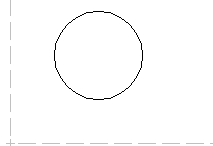
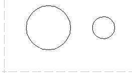
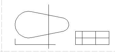
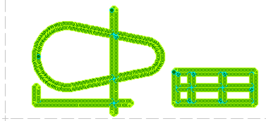
The Layout could be prepared singleline.
This could be imported from other systems, or designed direct with BESgrav:
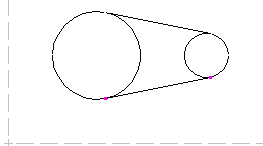
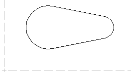
Contours could cross each other, it is not necessary a special preparation of the intersections:
Some times it is necessary to deform the construction a little to adjust some production parameters.
With BESgrav this is possible. Circles will become ellipses then.
- You may import designs from other systems, the could also be in bitmap format, they then will be
transformed into geometric outlines automatic.
- For the computation the following parameters are needed:
- No. of the tool
The geometric data of the used tool.
Each tools you need only to define one time in BESgrav.
Later you need only to input the no. of the tool which you want to use.
for the production of the gumption sheet metals only the No. of the tool is to be indicated.
If several tools are used, the latest defines the geometry of the cut. - The highness of the cut
There are up to 10 differently high cuts in one workpiece possible.
Lines with different height are specified by different levels.
E.G..
Layer 1 0,4 mm
Layer 2 0,3 mm
Layer 3 0,35 mm
The outlines are to be assigned to the different layers.
- Now the computation my start.
The computation takes 4 steps.
Normal all steps would be done at once.
If you want to search for mistakes in the outline, you may do it step by step. - Calculation step
Controlling the outline on errors. - Calculation step
Corners round.
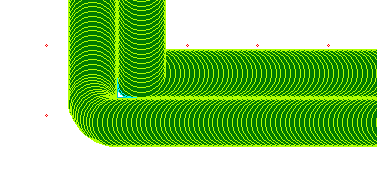
Corners cannot be prepared accurately with a round tool.
Rising the tip of the tools reduces the problem, but a little problem will stay:
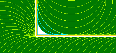
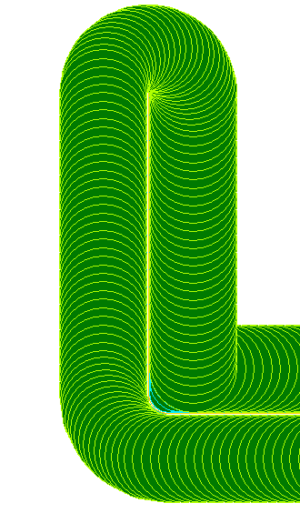
The corner above with more zoom:
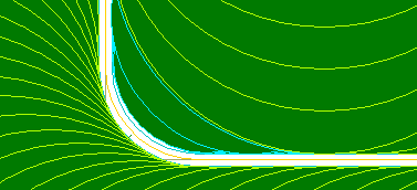
If the corner is rounded a little, the problem is reduced:
The blue circles show the rising of the tool tip in the "round corner".
The radius of the toop tip defines the needed radius of the corner.
Plus of rising the tool tip is, finer details may be procuded.
Minus of it is, the machine must stop on the beginning and end of a 3D movement. - Calculation step
Computation of a Outline
Tool pathes may be calculated by BESgrav and other programms only at the borders of areas.
A line has width of zero, computations with zero and allocation if running right or left,
inside or outside an open line is very difficult.
Therefore most programs calculate with areas, means closed lines.
The cuts are designed often as individual lines.
It is necessary that the computation for the tools gets an outline.
This will be prepared automatic in contructions like this:
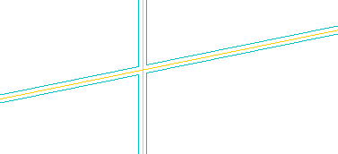
E.G. at a crossover of two lines the outline will be created automatic by BESgrav: Yellow: Center LINE - Blue: Outline
Branching:
Intersection line/circular arc: - Open ends are closed with a 180° circle:
- Calculation step
Computation of the tool path
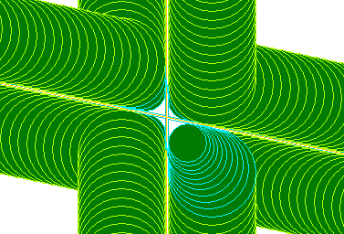
Each cut is worked out on two sides. Detail crossover of two outlines:
By the blue circles the 3D movement is to be recognized.
As is to be seen here, no roundness is possible at outline intersections. Here remain remainder and thus an inaccurate cut. An improvement is only possible by more small tools.
Detail of a freely ending knife, with a rounded corner:
The Outline wich is needed for calculation has only a distance of 0.01 mm.
When sending the tool path information to the machine, this little distance
is reduced to zero to get no mistake in the result.
Some other parts need a wide on the top of the knive, it is also possible to create such parts.
- Manufacturing
If you use the controller BES/C or BES/S4 to manufacture the flexible dies, you may use some features: - Measurement of ticks/orientation crosses.
The position of the plate on the machine may be captured, the real position is used to position the tools. - The tools are measured with a laser.
Using laser technics it is possible to measure the tools very exakt, tolerances in the tools are reduced. - The machine table may have little ups and downs, this may be scaned in into the machine controller.
A correction of machine table errors will be calculated inside BESgrav. - Very large workpieces may need more than one tool for each process.
A time (distance) could be defined inside BESgrav,
after this time the used up tool automatic will be replaced against a new one. - Controlling the ready flexible dies.
Using laser, after work the plate could be captured and a report of the real precision will be printed.
