-
Using a camera to identify the real position of the workpiece.
Reference marks / fiducials and also a simple hole may be used to define points on the workpiece.
The machine moves with the camera near to the reference mark, the picture is analyzed by BESgrav and the real position is calculated.
It is possible to compensate- Position
- Rotation
- Scaling
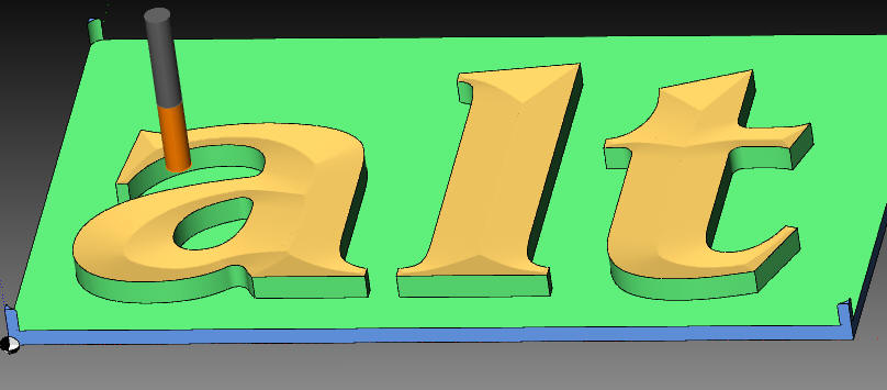
- Simulation3D:
- Engraving DataMatrix Code:

Also round for industries use :
- An easy form of automatic dimensioning is now available:

- A new Tool Outline:
You may realize mosaics:


Start with single line, use the outline tool to get an outline. Use the inner lines to produce the parts of the mosaic.
Enlarge single line constructions in with different distance.
- Manufacture a thread by milling. (With a special milling utter, not with a drill tap):
- Engraving pictures in two layered plates.
This principle may also be used to produce casting molds with which objects for imposing visual effects could be manufactured. E.g. if you want the face of your wife in the wall of your house.
Also be used to get molds to produce paper with watermarks.
The picture could be produced with lines (a rectangle picture) or with concentric circle / spiral (round picture):
- Use of Unicode characters for text input and field layout. Multiple text lines may be taken from another program in one action. Fast takeover using the Clipboard, not necessary to use dialog.
- Functions to manufacture Braille Alphabet with real sphere dots.
Also features which help construction and mounting of letters for blind people.
Normal characters are displayed together with the Braille letters to get a better overview, but they are not manufactured:
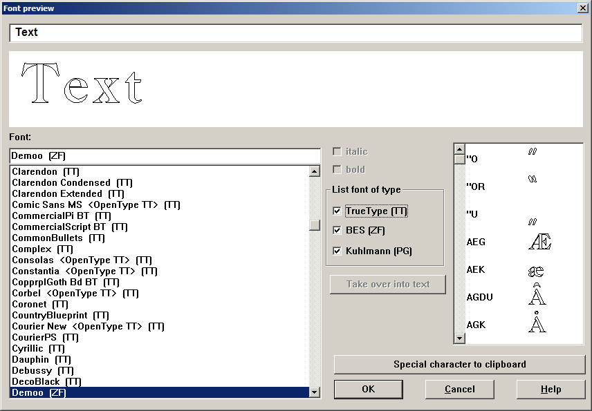
- Preview for character fonts (TrueType and also fonts for Engraving). While selecting a font, you see a graphic preview inside the dialog. If an engraving font is selected, also a table with the included special characters is shown.
- Preview while opening a file with a workpiece. One dialog with details of each file and one preview for the selected file. An other dialog with many previews, but no details. Sorting by name ore date may be selected.
Example:
- Resolve field layout into text lines, resolve text lines into contours, resolve scale with text into text and contours
- DXF import - Unicode is supported - Codepages are supported and translated by code tables
- Spline
Construct curves, also edit them (move, create and delete knots). Convert a polyline into a Spline.
- Test run (check machine output on screen): Now it is possible to step back and to zoom in and out. Moves are shown in an extra color.
- Zoom with mouse wheel (Added to the existing functions)
- Scroll the 2D graphic by mouse key or cursor key (Scroll bars of old program version are removed to get more space)
- Help points to adjust objects to each other. E.g. to adjust a text horizontal under the middle of a hole.
- Pattern Different line types possible. May be defined by a table.
- Layers may get names to get a better overview
- Tool to open a contour at a node
If an arc is selected, one end of the arc is fixed, the other end may be moved. After editing an arc will remain (in old version arcs are converted into a line).
Also new: Define a new length of a line without changing the angle.
- Use variables in Workpiece List: Workpiece List: Kombinate different workpieces on one plate
- Variable / calculate
- Structure of a variable name A variable consists followed of a letter from further letters or numbers. Up to 30 indications are possible as variable names. As the first indication can also underlined stand (_). this is however for the future in connection with subroutine technology and local variables reserved. Small and capital letters are not differentiated. I.e. it unimportant whether you write variable names in small or capital letters. Examples of valid variables:
ABC
A3344
LongName Command or function names cannot be used however as variable names! So OFFSET or SIN is not permissible as variable names. - Range of values
In a variable floating-point numbers with the range of validity are stored from 8.43E-37 to 3.37E+38. - Creation of a variable
With the first use of a name on the left side of an expression (a compute statement) put on a new variable automatically. A separate agreement is not necessary. That means it however that you may not use up yourselves with the variable names on the left side. Because with differently reading name a new variable is put on immediately. - Calculating with variables
As calculation methods the basic operations of arithmetic including clips, built-in functions are available like the trigonometric functions, and special functions. Per line an assignment may stand. On the left of the goal variable followed of an equals sign and on the right of the expression. E.g.:
A3344 = ABC + 33
Valid operators for the basic operations of arithmetic are
+ for addition
- for subtraction
* for multiplication
/ for division The computation within an expression takes place with priority for multiplication and division. If you want to break through this priority, you must use brackets.
Example:
A3344 = (ABC + 3.3) * 5 Still another important note: They must enter as decimal point one point and no comma. The comma is reserved for separating the parameters with function calls. - Functions
- Built-in functions
Built-in functions like it also in the DPL are defined
Trigonometric functions SIN, COS, TAN, ARCSIN, ARCCOS, ARCTAN
as well as ATAN2 for forming an angle from x and y-component. ABS absolute value of a number (sign one takes away
SQRT root from a number
EXP natural exponential function
LN natural algorithm
SQR squaring a number
SIGN sign of a number (from positive numbers will +1, from negative becomes -1)
TRUNC integral portion of a number
ROUND number rounded on whole number - Special functions of the workpiece list:
Selections the workpiece point of reference:
ReadPRPX
ReadPRPY
ReadPRPZ
ReadPRPA
ReadPRPB
ReadPRPC
ReadPRPU
ReadPRPV
In each case the workpiece point of reference including offset from the manual control is read
z. B.
XBezug = ReadPRPX
YBezug = ReadPRPZ
Likewise the palpation functions belong to the special functions
SENZV
SENZABSV
SENZV3
SENZABSV3
Explanation for this under 2.2 Selections of the X/Y position of the highest point from the surface dialogue:
ReadSurfaceHX
ReadSurfaceHY
Use: Material surface regulation of a scanned free forming surface.
Parameters of a function must be written in round parentheses. Several parameters are separated by comma.
z. B.
S = SIN(30)
Distance = SQRT(SQR(XTeil) + SQR(YTeil) ) - Instructions for scanning special points on the machine
- Scanning and immediate correcting of the workpiece point of reference
So far already the instructions SENZ and SENZABS contained in the workpiece list remain unchanged. They are described in the operating instructions and/or in the on-line assistance. - Scanning by function, no immediate correcting of the workpiece point of reference
- keys relative to the workpiece point of reference
For this the function calls SENZV and SENZV3 are available. With both functions the point of scanning will hand over as parameter related to the workpiece point of reference. With the function SENZV3 the starting point for scanning is added.
The result is assigned to a variable.
With the line
ZWert = SENZV(100, 30.5)
at position X=100 Y=30.5 a scan will be done. The two values refer to the workpiece point of reference. The result is put down in the variable ZWert. Here the difference stands to the workpiece point of reference in Z this value can with the offset instruction be used.
You find an example of the use of the instruction SENZV in the file Tasten_Offset.WSL. With the line
ZWert = SENZV3(100, 30,5, 80)
the same position for scanning is implemented. However the tracer will proceed independently of the dialogue attitude for starting point in Z to the value 80 mm (related to machine zero). - Scans related to machine zero point
For scanning related to the machine zero point the function calls stand SENZABSV and SENZABSV3 for order. For these two functions you indicate the point of palpation in X/Y related to the machine zero point. With the function SENZABSV3 the starting point is added into Z for groping.
The result of the scanning procedure is assigned to a variable.
With the line
ZWert = SENZABSV(200.3, 85.8)
at position 200,3 in X and 85,8 in Y related to the machine zero point one gropes. The result is assigned to the variable ZWert. The palpation result refers likewise again on the machine zero point.
You find an example of the use of the instruction SENZV in the file Tasten_Absolut.WSL. - Drive the tracer in and out
With the first call of the SENZxxx functions the tracer is driven out. Opposite the SENZ and SE Z starting from self-service Z remains driven out the tracer after groping. If you do not program the instruction SENZIN, the tracer is again brought in automatically with the first Engrave instruction. - Instruction for bringing the tracer in
For this the instruction SENZIN is available. No parameters. - Other instructions
- Representation of variables
The DEBUG instruction may be used to see some interim results. The use of this instruction is meaningful also after groping material surfaces. So you can examine the palpation values for plausibility, before the milling procedure is started. The values and texts are represented in a Windows Message box. The workpiece list is only then continued to process if you confirm the Messagebox. An abort of the workpiece list is likewise possible in this condition. As parameter first a number comes. This number serves logging to file for future extensions within the range. They should here always use the number of 0. Subsequently, a number of texts comes into "" and/or variables. The number is only limited over the maximally permissible line length by 1000 indications.
Example:
Debug 0 "ZWert1 =", ZWert1, " ZWert2 =", ZWert2
Here the two variables ZWert1 and ZWert2 are represented once as text and once as number into a Messagebox. If you would like to have the representation in the Messagebox of several lines, then you can insert in the text \n. For above example would look in such a way:
Debug 0 "ZWert1 =", ZWert1, "\nZWert2 =", ZWert2 - Scale Inch / mm
In the workpiece list the scale from the dialogue window option/pre-setting applies to the length specifications. Independently of it you can switch to another scale. - Setting to inch
After call of SET INCH you must enter all following parameters in inch. That applies to length values. Angles and factors are not concerned. - Setting to millimeter
After call of SETMM you must enter all following parameters in millimeters. That applies to length values. Angles and factors are not concerned.
- Special features are included to manufacture punching knifes for flat or rotating punch plates, with which cardboards, labels and stickers are produced.
- Undo and Redo for all constructions, all edit functions and many dialogs (Old version only undo for deleting)
- Tool tips (Move mouse on tool button, information about the tool appears in a bubble)